
Table of Contents
- What Makes 3D Modeling Software Right for Mechanical Parts
- Parametric vs. Direct Modeling for Mechanical Parts
- Best CAD Software for 3D Printing
- Free Mechanical CAD Software Options
- Essential Features for Mechanical Design Software
- Assembly Design and Simulation Capabilities
- Choosing the Right Software for Your Workflow
- Conclusion
- Frequently Asked Questions
Last Updated: October 1, 2026
What Makes 3D Modeling Software Right for Mechanical Parts
Choosing the best 3D modeling software for mechanical parts depends on what you're actually building and how you plan to manufacture it. The wrong tool wastes time. The right one makes design faster, more accurate, and production-ready from day one.
Mechanical design software falls into distinct categories. Some excel at rapid prototyping for 3D printing, others prioritize precision for CNC machining, and a few handle both equally well.
The key difference is how the software handles geometry, assembly workflows, and file exports. A tool optimized for 3D printing might struggle with tolerancing for metal parts; software built for industrial manufacturing might feel bloated for simple designs.
Parametric vs. Direct Modeling for Mechanical Parts
Parametric and direct modeling represent two fundamentally different approaches to mechanical design.
Parametric modeling builds designs on a foundation of constraints and relationships. You define dimensions, then create features based on those dimensions. If you change a dimension, every dependent feature updates automatically. This approach excels when you're designing parts with precise tolerances or when you need to explore multiple variations quickly.
Parametric modeling excels in manufacturing by maintaining relationships between features, ensuring a mounting hole stays centered relative to edges, for example. Design intent is captured in the model itself.
Direct modeling lets you push geometry around intuitively without setting up constraints first. It feels faster for one-off designs and organic shapes, and is forgiving during rapid iteration.
For manufacturing, parametric modeling typically wins. For 3D-printed decorative pieces or quick prototypes, direct modeling often feels more natural.
Most professional tools blend both approaches. The question isn't which is better, it's which matches your typical workflow.
Best CAD Software for 3D Printing
3D printing and CNC machining have opposite design constraints. Choosing software without considering your manufacturing endpoint leads to wasted iterations and failed parts.
For 3D printing (additive manufacturing), your software priorities are:
- Clean manifold geometry: Your STL export must have no internal errors, non-manifold edges, or self-intersecting faces. FreeCAD and Blender occasionally export geometry that slicing software flags as unprintable; test with a small print before committing to production work.
- Wall thickness visualization: Thin walls (under 1.5 mm for FDM, under 0.8 mm for resin) fail during printing. Fusion 360 includes a built-in wall thickness checker; FreeCAD requires manual measurement or plugins. This feature saves hours of failed prints.
- Orientation and support planning: Some tools (Fusion 360, Meshmixer) preview build platform orientation and support material; others require handling this in slicer software.
- Rapid iteration on feature size: Parametric tools (Fusion 360, FreeCAD) let you change a global dimension and rebuild the entire model. Direct modeling tools (Blender, Tinkercad) require manual adjustment of each feature.
Fusion 360 handles 3D printing workflows well, exports STL and OBJ natively, includes wall thickness analysis, and offers a free tier for personal and startup use.
FreeCAD is open-source and free with no file-size or complexity limits. It exports to all standard formats and has an active community building 3D printing tools, though the interface is less intuitive than commercial alternatives.
Tinkercad is browser-based and designed for rapid design and immediate STL export. It's excellent for simple mechanical assemblies and creative projects, though not for precision engineering.
Blender has grown strong CAD capabilities alongside its 3D art tools. It excels at generating print-ready geometry from organic shapes and blending artistic and mechanical requirements.
For CNC machining (subtractive manufacturing), your priorities shift:
- Precise tolerancing: Your software must support tolerance annotations and maintain dimensional accuracy through export. Parametric tools excel here; direct modeling tools often lose precision during conversion.
- STEP file compatibility: Manufacturers expect STEP format with preserved feature history and tolerance data. STEP is the industry standard; proprietary formats lock you into specific software.
- Tool path preview: Some tools (Fusion 360, FreeCAD with CAM plugins) simulate CNC cutting and catch tool-part collisions before machining.
- Material-specific design rules: Your software should support material libraries and stress analysis to catch designs that will fail in service.
Fusion 360 bridges both worlds effectively with clean STEP export, CAM tools, and tolerance support. For designers moving between 3D printing and CNC work, Fusion is the most practical choice.
FreeCAD with the Path Workbench can generate tool paths, but the workflow is less polished than commercial CAM software. For outsourced CNC machining, Fusion 360 is more reliable.
The critical difference: 3D printing tolerates organic geometry and rewards thin walls; CNC machining demands precise geometry with generous wall thickness. Choose software optimized for your primary manufacturing endpoint.
Free Mechanical CAD Software Options
Budget constraints are real. Several free tools deliver genuine capability for mechanical design.
FreeCAD remains the most capable free option. It's parametric, handles assemblies, exports to industry-standard formats, and has active development. The interface takes time to learn, but it's genuinely professional software with no limitations based on file size or complexity.
Fusion 360 offers free licenses for personal, educational, and startup use. If you qualify, you get commercial-grade software at no cost. The limitation is licensing, you must stay within the qualifying category. For hobbyists and small shops, this is often workable.
OpenSCAD is code-based modeling. You write geometry as text commands. This approach appeals to programmers but frustrates designers accustomed to visual interfaces. It's powerful for parametric design and reproducible workflows, but the learning curve is steep.
Tinkercad is free and browser-based. It's limited compared to professional tools, but it's approachable and fast. For simple mechanical projects, it's often sufficient.
The trade-off with free tools is usually support and learning resources. Paid software comes with documentation, tutorials, and community forums staffed by experienced users. Free tools have communities too, but they're smaller and response times are slower.
Essential Features for Mechanical Design Software
Certain capabilities separate adequate tools from ones that genuinely accelerate mechanical design work. But features alone don't tell the full story, how those features perform depends on your hardware and manufacturing endpoint.
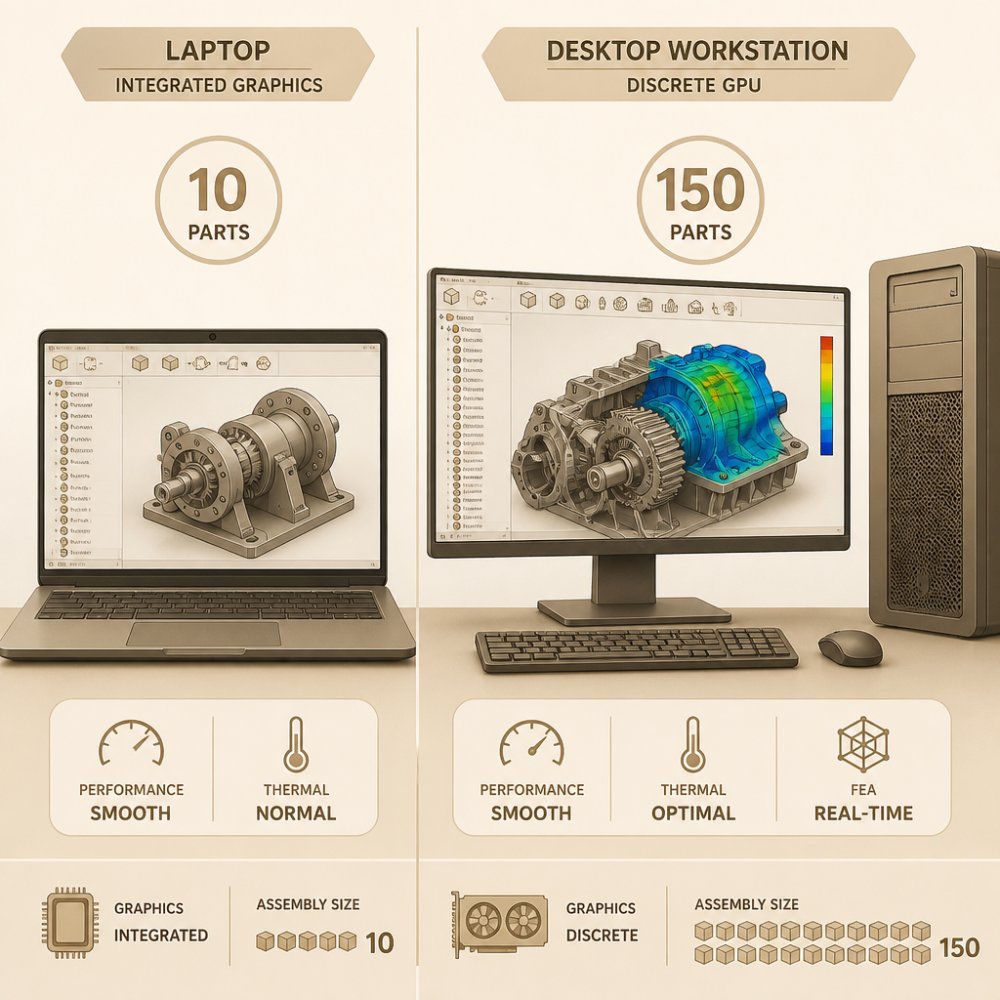
Parametric modeling lets you capture design intent; changes propagate automatically. For mechanical assemblies with 50+ parts, expect to need at least a quad-core processor and 16 GB of RAM; 32 GB for designs exceeding 200 parts.
Assembly design constrains parts relative to each other, detects collisions, and verifies fit. GPU acceleration matters here. Integrated graphics work for small assemblies under 20 parts; discrete GPUs (NVIDIA GeForce GTX 1650 or better) become essential for assemblies exceeding 100 parts.
Surface modeling matters when you're designing organic shapes or complex curves. Not every mechanical part needs it, but when you do, the absence of surface tools is crippling. Surface operations are computationally expensive; expect 2-5 second rebuild times on mid-range hardware for complex surfaces with high patch counts.
Simulation and analysis let you test designs before manufacturing. Finite element analysis catches stress concentrations. Motion simulation verifies that mechanisms move as intended. These features accelerate iteration but are hardware-intensive. FEA on a 10,000-element mesh typically requires 8+ GB of available RAM and benefits significantly from multi-core processors. Running FEA on a dual-core machine can take 10-15 minutes; the same analysis on a six-core processor with 32 GB RAM completes in 2-3 minutes.
File interoperability is underrated but critical. Your software must read and write STEP, IGES, and STL files cleanly. If your manufacturer uses a different tool, you need to exchange files reliably. This also matters for long-term file ownership: proprietary formats (like SolidWorks .sldprt) lock you into a specific tool; open formats like STEP are readable by nearly every mechanical CAD package.
Rendering helps communicate design intent. Being able to generate realistic images of parts before manufacturing saves revision cycles. Real-time rendering is GPU-dependent; CPU-based rendering (used by some free tools) can take 5-30 minutes per image on standard hardware.
Manufacturing-specific export options are often overlooked but essential. For 3D printing, your software must produce clean, manifold STL geometry and ideally preview wall thickness to catch thin-wall failures before printing. For CNC machining, you need STEP export with preserved tolerances and the ability to generate tool paths or export to CAM software. For sheet metal work, you need unfolding tools and DXF export. Choose software that prioritizes the manufacturing process you'll actually use most.
Assembly Design and Simulation Capabilities
Assembly design separates tools meant for individual parts from tools meant for complete products. The difference matters when you're designing systems where multiple components interact.
Choosing the Right Software for Your Workflow
The best 3D modeling software for mechanical parts is the one that matches how you actually work.
Conclusion
The best 3D modeling software for mechanical parts depends on your specific design goals, manufacturing process, and budget. Parametric tools like Fusion 360 excel for precision and manufacturing workflows. Direct modeling tools work well for rapid prototyping. Open-source options like FreeCAD deliver professional capability at no cost.
Frequently Asked Questions
What is the best software for 3D mechanical modeling?
The best 3D modeling software for mechanical parts depends on your workflow and budget. Professional-grade options like SOLIDWORKS and Fusion 360 dominate mechanical engineering because they handle parametric modeling, assembly design, and integration with manufacturing processes. For 3D printing specifically, software that exports STL files and supports topology optimization works best. Evaluate based on whether you need parametric or direct modeling, assembly capabilities, and compatibility with your manufacturing method.
Is there free 3D modeling software for mechanical parts?
Yes, several free mechanical CAD software options exist. FreeCAD offers parametric modeling and assembly design without cost. Fusion 360 provides a free version for personal use and startups, including cloud collaboration and rendering. Blender is powerful for organic shapes but requires more learning for mechanical precision. LibreCAD focuses on 2D drafting. Free options work well for hobbyists and small projects, though professional teams typically invest in commercial software for technical support and advanced features like finite element analysis.
What features should I prioritize when selecting CAD software for mechanical design?
Prioritize parametric modeling for design flexibility, assembly design capabilities for multi-part projects, and file interoperability (STEP and IGES support). If you're designing for 3D printing, ensure STL export and mesh generation are included. Look for simulation tools like kinematic simulation and finite element analysis if you need design validation. Cloud collaboration features speed up teamwork, while rendering engines help visualize final products. Consider your manufacturing workflow, CNC machining and 3D printing have different software requirements.
What's the difference between parametric and direct modeling for mechanical parts?
Parametric modeling builds designs using defined rules and dimensions that update automatically when you change values, making it ideal for iterative mechanical design and engineering documentation. Direct modeling lets you push, pull, and reshape geometry freely without constraints, which is faster for quick iterations but less flexible for design changes. Most professional mechanical CAD software offers both approaches. Parametric modeling is preferred for precision parts and manufacturing because it maintains geometric dimensioning and tolerancing throughout the design process.
0 comments