
Table of Contents
- What Are Layer Lines?
- Why Layer Lines Form During 3D Printing
- Best Layer Height for 3D Printing Quality
- Mechanical Causes: Belts, Pulleys, and Lead Screws
- Extrusion and Flow Rate: Getting Consistent Output
- How to Hide Layer Lines on 3D Prints
- Print Speed, Cooling, and Thermal Stability
- Minimizing Layer Lines: A Step-by-Step Approach
Last Updated: August 23, 2026
What Are Layer Lines?
Layer lines are the horizontal ridges and visible seams that appear on 3D-printed objects. They form because fused deposition modeling (FDM) builds objects one thin horizontal layer at a time, and each layer of extruded plastic doesn't bond perfectly flush with the layer below it.
If you've ever run your finger across a 3D print and felt distinct horizontal grooves, you've felt layer lines. They're one of the most common quality complaints from people new to 3D printing, though they're a fundamental characteristic of how additive manufacturing works.
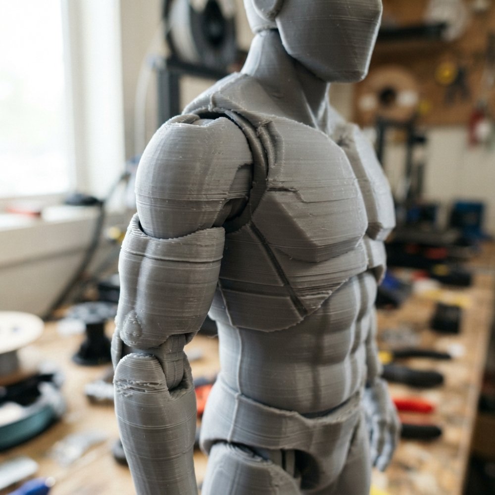
The visibility of layer lines depends on several factors: your layer height setting, print speed, nozzle temperature, and mechanical calibration. A 0.2mm layer height will show more pronounced lines than a 0.1mm setting. Understanding layer lines is the first step toward controlling them.
Why Layer Lines Form During 3D Printing
Layer lines exist because of how fused deposition modeling works. The printer extrudes molten plastic through a nozzle, moving in the X and Y directions to draw each layer's outline and fill. Once that layer is complete, the Z-axis moves up by your specified layer height, typically 0.1mm to 0.4mm, and the process repeats.
Each layer is a discrete step. The plastic cools and hardens, but it never bonds perfectly flush with the layer below. There's always a small gap or ridge where one layer ends and the next begins. Uneven cooling worsens this problem, if the top of a layer cools faster than the sides, it contracts slightly, creating a visible ridge.
How Fused Deposition Modeling Creates Horizontal Artifacts
FDM builds the object one horizontal slice at a time. Unlike resin 3D printing, which cures an entire cross-section at once, this approach inherently creates visible layer lines. The nozzle deposits a thin bead of plastic, it cools and hardens, the Z-axis moves up, and the process repeats. Every transition between layers creates a potential surface artifact.
The smaller your layer height, the more layers you need to print, and the longer the print takes. The larger your layer height, the faster you print, but the more pronounced the lines become.
The Role of Z-Axis Movement
The Z-axis controls vertical movement. If your Z-axis isn't perfectly calibrated, or if the lead screw is bent, or if the belts are loose, the Z-axis won't move smoothly. This creates Z-wobble, a periodic variation in layer height that produces wavy, irregular lines instead of straight ones.
Z-wobble is one of the most frustrating layer line problems because it's mechanical, not a setting you can fix in your slicer. A loose pulley, a worn bearing, or a bent lead screw will cause Z-wobble. The lines won't be evenly spaced; they'll have a wave pattern that makes the print look worse than it actually is.
Best Layer Height for 3D Printing Quality
Your layer height is the single most important setting for controlling layer line visibility. It's a direct trade-off: smaller layer heights produce less visible lines but take longer to print. Larger layer heights print faster but show more pronounced lines.
Standard vs. Fine Layer Heights
A 0.2mm layer height is the industry standard. Most prints look acceptable at this setting. A 0.1mm layer height produces noticeably smoother surfaces with finer, less pronounced lines, but print time doubles or triples. A 0.3mm or 0.4mm layer height is for speed, useful for prototypes or test prints where surface finish doesn't matter.
The choice depends on your priorities. For decorative prints or display pieces, 0.1mm or 0.15mm is worth the extra time. For functional brackets or prototypes, 0.2mm or 0.3mm is sufficient.
Adaptive Layer Height Settings in Your Slicer
Modern slicers like Cura and PrusaSlicer offer adaptive layer height, which automatically adjusts layer height based on model geometry. Flat surfaces use larger layers to save time. Curved surfaces and details use smaller layers to preserve detail. This can reduce print time by 15-30% compared to a fixed small layer height while maintaining good surface quality on detailed areas (ultimaker.com).
Mechanical Causes: Belts, Pulleys, and Lead Screws
If your layer lines look wavy, irregular, or asymmetrical, the problem is usually mechanical. The most common culprits are loose belts, worn pulleys, or a bent lead screw on the Z-axis.
Detecting Z-Wobble and Loose Components
Z-wobble appears as a repeating wave pattern in your layer lines. To check for Z-wobble, print a tall, narrow test object like a calibration tower and look at the sides. If the layer lines have a regular wave pattern, you have Z-wobble. If the lines are straight and evenly spaced, your Z-axis is fine.
Loose belts on the X and Y axes can cause other surface artifacts. Check belt tension by pressing on the belt midway between pulleys, it should have slight give, about a quarter inch of deflection, but not be loose.
If you suspect a bent lead screw, remove it and roll it on a flat surface. A bent screw will rock. If it's bent, replace it. Lead screws are inexpensive and easy to swap out on most printers.
Extrusion and Flow Rate: Getting Consistent Output
Inconsistent extrusion produces visible ridges and surface imperfections that look like layer lines but are actually caused by uneven plastic flow. If your filament diameter varies or your flow rate isn't calibrated, you'll see thicker and thinner lines on your print.
Filament Diameter Consistency and Under-Extrusion
Filament diameter is supposed to be 1.75mm or 2.85mm, depending on your printer. Cheaper filament might vary by 0.1mm or more. This variation directly affects how much plastic is extruded. If your actual filament is thinner, less plastic will come out of the nozzle, resulting in under-extrusion with thin, weak lines.
If you suspect under-extrusion, use digital calipers to measure several spots along the filament. If the diameter varies by more than 0.05mm, the filament is poor quality. If the filament diameter is consistent, the problem might be your nozzle. A partially clogged nozzle restricts flow and should be cleaned or replaced.
How to Hide Layer Lines on 3D Prints
If your prints have visible layer lines and you want a smooth surface finish, post-processing techniques are most effective. You can sand the print, use chemical smoothing, or paint over the lines.
Sanding 3D Prints for a Smooth Surface Finish
Sanding is the most straightforward way to hide layer lines. Start with coarse sandpaper (120-150 grit) to remove the bulk of the ridges. Then progress to finer grits (220, 400, 600) to smooth the surface. For small prints, hand sanding works fine. For larger prints, a belt sander or orbital sander saves time.
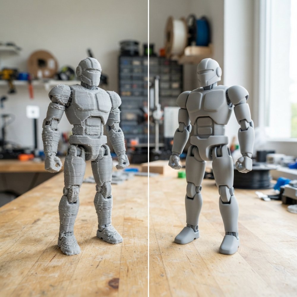
The key is patience and progression. Each grit removes the scratches from the previous grit. After sanding, restore shine with a clear coat or polish.
Acetone Vapor Smoothing and Other Post-Processing Methods
Acetone vapor smoothing works on PLA and ABS prints. You expose the print to acetone vapor (not liquid acetone, which dissolves the plastic too aggressively). The vapor slightly melts the surface, smoothing out the layer lines. Place the print in a sealed container with a small amount of acetone. Timing is critical; most prints need 10-30 minutes depending on size and material.
Acetone vapor smoothing works best on ABS and is less effective on PLA. Other materials like PETG don't respond well. Other post-processing methods include epoxy or polyurethane resin coating to fill surface imperfections, and primer and paint to hide remaining layer lines. For most people, sanding followed by a clear coat is the best balance of effectiveness and simplicity.
Print Speed, Cooling, and Thermal Stability
Print speed affects layer line visibility more than most people realize. Faster print speeds mean less time for each layer to cool before the next layer is applied, affecting how well layers bond and how defined the layer lines are.
How Cooling Fan Speed Affects Layer Adhesion
The cooling fan cools the plastic as it's extruded, helping it solidify quickly for better detail and precision. But too much cooling creates weak layer adhesion, the top of each layer cools so fast that it contracts, pulling away from the layer below.
For the first few layers, reduce cooling to 20-30% to ensure good adhesion to the print bed. For the rest of the print, 50-100% is typical. Higher cooling speed produces crisper, more defined layer lines. Lower cooling speed produces softer, less defined lines because the plastic stays warm longer and blends slightly.
Nozzle Temperature and Thermal Expansion
Nozzle temperature directly affects how the plastic flows and cools. Higher temperatures mean more fluid plastic, which blends layers together. Lower temperatures mean stiffer plastic, which creates more defined layer lines.
Standard nozzle temperatures are 200-210°C for PLA and 230-250°C for ABS. If you're seeing weak layer adhesion, try increasing temperature by 5°C. If you're seeing blobby, undefined layer lines, try decreasing temperature by 5°C.
Minimizing Layer Lines: A Step-by-Step Approach
If you want to minimize layer lines on your prints, follow this workflow:
Step 1: Check your printer's mechanical condition. Verify that belts are tight, pulleys spin freely, and the Z-axis moves smoothly. Print a Z-wobble test tower and inspect the results.
Step 2: Calibrate your nozzle height. Use a bed leveling test print or the paper method to ensure consistent nozzle height across the print bed.
Step 3: Reduce layer height. Set your layer height to 0.1mm or 0.15mm. This is the most effective single change for reducing visible layer lines.
Step 4: Adjust print speed. Reduce print speed to 40-50mm/s. Slower printing gives the plastic more time to cool and bond properly.
Step 5: Optimize cooling. Set cooling fan speed to 50-75% for the main print body. Reduce cooling to 20% for the first 5-10 layers to ensure good bed adhesion.
Step 6: Fine-tune nozzle temperature. Start at the filament manufacturer's recommended temperature. If you see weak adhesion, increase by 5°C. If you see blobby lines, decrease by 5°C.
Step 7: Test and iterate. Print a small test object and inspect the surface. Make one change at a time and print again.
Step 8: Post-process if needed. If layer lines are still visible after optimizing settings, sand the print or use vapor smoothing.
The key is understanding that layer lines result from a combination of factors. No single setting will eliminate them completely. The best approach is to reduce them through settings, then use post-processing to hide what remains.
Layer lines are a fundamental part of how 3D printing works, but they don't have to ruin your prints. Proper settings and post-processing can produce smooth, professional-looking results. Whether you're printing desk buddies, gaming figures, or custom projects, understanding the causes of layer lines and how to minimize them will help you achieve the quality you're after. Start with mechanical checks, adjust your slicer settings, and use post-processing techniques like sanding to refine your final product. For example, check out the Absolute Batman 3D Wall Display Poster or the Halo 3 Master Chief 3D Wall Display for high-quality, detailed 3D-printed products. For detailed guidance on 3D printer calibration and maintenance and comprehensive slicer documentation, consult manufacturer resources to ensure your specific printer is optimized for quality prints.


| Setting | Impact on Layer Lines | Best for Quality |
|---|---|---|
| Layer Height (0.1mm vs 0.2mm) | Smaller = less visible lines | 0.1mm for detail work |
| Print Speed (30mm/s vs 60mm/s) | Slower = better adhesion | 40-50mm/s for quality |
| Cooling Fan (30% vs 100%) | Moderate = balanced finish | 50-75% for most materials |
| Nozzle Temperature | Higher = softer lines, lower = sharper | Filament manufacturer spec ±5°C |
| Z-Axis Calibration | Loose components = wavy lines | Tight belts, smooth movement |
=== FAQ ANSWERS (audit these too, same rules) ===
[1] Q: Are layer lines normal in 3D printing? A: Yes, layer lines are a natural result of how fused deposition modeling works. Every 3D printer builds objects one horizontal slice at a time, and these layers stack on top of each other. The visible ridges you see are the edges where each layer meets the next. Even high-end printers produce some layer lines, the goal is to minimize them through proper settings and post-processing, not eliminate them entirely.
[2] Q: What's the best layer height for 3D printing? A: Standard layer heights range from 0.2mm to 0.3mm for most FDM printers, offering a balance between print speed and surface finish. Finer details benefit from 0.1mm to 0.15mm layer heights, though these take significantly longer. For articulated figures and collectibles where surface finish matters, start with 0.2mm and experiment with your slicer's adaptive layer height feature, which automatically adjusts height based on model geometry.
[3] Q: Can you sand away 3D print layer lines? A: Absolutely. Sanding is one of the most effective post-processing methods for hiding layer lines. Start with coarse sandpaper (80-120 grit) to remove major ridges, then progress to finer grits (220-400+) for a smooth surface finish. For intricate articulated figures, use sanding sponges or fine detail sanders to reach curved areas. Pair sanding with chemical smoothing methods where appropriate for the material to achieve a nearly seamless surface.
[4] Q: What causes horizontal lines on 3D prints? A: Layer lines form because additive manufacturing builds objects in discrete horizontal slices. Several factors intensify their visibility: inconsistent extrusion, thermal expansion from nozzle temperature fluctuations, loose mechanical components like belts or lead screws, and filament diameter variations. Z-wobble, irregular z-axis movement, creates particularly noticeable horizontal artifacts. Checking your printer's mechanical calibration and adjusting cooling fan speed can reduce their prominence.
Frequently Asked Questions
Are layer lines normal in 3D printing?
Yes, layer lines are a natural result of how fused deposition modeling works. Every 3D printer builds objects one horizontal slice at a time, and these layers stack on top of each other. The visible ridges you see are the edges where each layer meets the next. Even high-end printers produce some layer lines, the goal is to minimize them through proper settings and post-processing, not eliminate them entirely.
What's the best layer height for 3D printing?
Standard layer heights range from 0.2mm to 0.3mm for most FDM printers, offering a balance between print speed and surface finish. Finer details benefit from 0.1mm to 0.15mm layer heights, though these take significantly longer. For articulated figures and collectibles where surface finish matters, start with 0.2mm and experiment with your slicer's adaptive layer height feature, which automatically adjusts height based on model geometry.
Can you sand away 3D print layer lines?
Absolutely. Sanding is one of the most effective post-processing methods for hiding layer lines. Start with coarse sandpaper (80-120 grit) to remove major ridges, then progress to finer grits (220-400+) for a smooth surface finish. For intricate articulated figures, use sanding sponges or fine detail sanders to reach curved areas. Pair sanding with chemical smoothing methods where appropriate for the material to achieve a nearly seamless surface.
What causes horizontal lines on 3D prints?
Layer lines form because additive manufacturing builds objects in discrete horizontal slices. Several factors intensify their visibility: inconsistent extrusion, thermal expansion from nozzle temperature fluctuations, loose mechanical components like belts or lead screws, and filament diameter variations. Z-wobble, irregular z-axis movement, creates particularly noticeable horizontal artifacts. Checking your printer's mechanical calibration and adjusting cooling fan speed can reduce their prominence.
This article was written using GrandRanker
0 comments