
Table of Contents
- Start With Shape Analysis and Part Connection Strategy
- Master 3D Printing Tolerances and Clearances for Tight Fits
- Design 3D-Printed Snap-Fit Joints for Easy Assembly
- Designing 3D-Printed Hinges and Articulated Connections
- Create 3D Printing Test Fit Models Before Full Production
- Design Large Objects as Multiple Parts for Strength and Printability
- Improve Assembly Strength and Durability
- Frequently Asked Questions
Last Updated: October 7, 2026
When you're applying tips for designing 3d printed interlocking parts, the gap between a perfect fit and a frustrating mess is often just a few millimeters. At Bandit's Print Den, we've helped countless customers create articulated figures, desk accessories, and custom projects where pieces snap together smoothly.

This guide covers tips for designing 3d printed interlocking parts: core principles, your printer's quirks, and the joint types that suit different situations.
Start With Shape Analysis and Part Connection Strategy
Before you open your CAD program, think about how your parts will connect. The shape of your interlocking features determines everything that follows.
Start simple. The most reliable connections use basic geometry: cylinders, rectangular slots, or tapered shapes. Avoid thin walls, sharp corners, and complex curves where parts meet.
Ask yourself three questions:
- Will these parts slide together or snap into place?
- Do I need them to separate later, or is this a permanent assembly?
- How much force will the connection experience during use?
Your answers shape the design.
Master 3D Printing Tolerances and Clearances for Tight Fits
Tolerance is the gap you deliberately leave between parts so they fit; clearance is the space between surfaces that aren't supposed to touch. Get these wrong and your parts either fall apart or lock together permanently, your printer doesn't print to exact dimensions, and every material shrinks differently.
Account for Printer and Material Variation
Consumer FDM printers typically hold ±0.5mm on small features, varying by brand, material, and settings; resin printers are tighter but still not injection-molded precision.
The real fix is designing around variation. Don't design a 10mm hole expecting a 10mm post to fit perfectly, design the hole 10.5mm and the post 9.8mm, then test to confirm.
Offset Your CAD Model Dimensions
Offsetting means deliberately making features larger or smaller to compensate for your printer's behavior.
Start with conservative offsets:
- Holes and slots: add 0.3mm to 0.5mm
- Posts and pins: subtract 0.3mm to 0.5mm
- Snap-fit arms: subtract 0.2mm to 0.3mm
These are starting points, not gospel, your printer and material may need different values, which is why test prints exist. Offset only the surfaces that touch; a 0.5mm offset to an entire part breaks everything else.
Design 3D-Printed Snap-Fit Joints for Easy Assembly
Snap-fits are flexible features that bend during assembly, then spring back to lock in place. They suit desk buddies, articulated figures, and toys because they allow repeated assembly and disassembly, but picking the wrong joint type is the most common reason a printed assembly fails.
Compare Joint Types Before You Model
Every interlocking connection trades off strength, printability, assembly effort, and removability. Use this comparison to pick the right one before you open CAD.
| Joint type | Strength | Printability | Assembly effort | Removable? |
|---|---|---|---|---|
| Snap-fit (cantilever) | Moderate | Needs clean overhang control | Low, one push | Yes, limited cycles |
| Press-fit (friction) | High | Easy, no undercuts | Moderate, needs force | Rarely without damage |
| Dovetail slide | High in shear | Easy if oriented flat | Low, slides in | Yes, if clearance is right |
| Pin and socket | Moderate | Easy, two parts | Low | Yes |
| Tab and slot | Moderate | Easy, flat | Low | Yes, if not glued |
| Living hinge (thin PP/TPU web) | Low to moderate | Very material-dependent | None, printed in place | No |
A few rules of thumb:
- If the joint must come apart more than a dozen times, favor a pin, dovetail, or tab over a snap-fit, snap-fit arms fatigue and crack at the flex zone.
- If the joint carries load in one direction only, a dovetail slide is stronger and easier to print than a snap-fit because it has no undercut.
- If the joint is permanent, a press-fit with a shallow barb or a drop of cyanoacrylate outperforms a snap-fit and prints faster.
Anatomy of a Snap-Fit That Survives
A snap-fit has four working features:
- Arm: a thin, flexible beam that bends during assembly
- Hook: a catch at the end that locks over a lip
- Undercut: the shape that prevents the arm from sliding back out
A reliable cantilever arm on a desktop FDM printer is typically 1.5 mm to 3 mm thick, 8 mm to 15 mm long, and tapers slightly toward the hook. The hook should be small and sharp with a 30 to 45 degree lead-in chamfer so it cams over the lip instead of jamming.
Match the Joint to the Material
Material choice changes which joint works. PLA is stiff and brittle, so snap-fit arms need to be thicker and shorter, and living hinges are a poor fit. PETG flexes further and tolerates a thinner arm. TPU and other flexibles can print a living hinge in place, but the thin web must run parallel to the layer lines.
Choosing Between Snap-Fits and Press Fits
Snap-fits are flexible and forgiving, ideal for parts that come apart, but they weaken over time and fail if flexed too often. Press fits are rigid friction connections, stronger and more permanent, but harder to assemble and nearly impossible to disassemble without damage. For articulated figures and desk buddies, snap-fits usually win; for structural connections that won't move, press fits are stronger.
Design the Undercut for Your Printer, Not for the Drawing
Undercuts are the hardest feature to print cleanly because they require bridging or support. Two fixes: rotate the part so the undercut faces up and prints as a bridge (a 0.5 mm to 1 mm undercut bridges reliably on most FDM printers at 0.2 mm layer height), or split the joint into two printed halves that sandwich together so no undercut is printed at all.
Designing 3D-Printed Hinges and Articulated Connections
Hinges let parts rotate around an axis. The key is the pin: a small cylinder that holds two parts together while letting them spin.
A simple hinge has two flaps (one on each part), a pin hole drilled through each flap, and a pin that slides through both holes.
For multi-axis articulation (like our T-Rex Dinosaur - Fully Articulating 3D Printed Dino | 2 Sizes), stack multiple hinges along the spine and test the range of motion before printing the full model.
XXL Flexi T-Rex Skeleton | 36" 3D Printed Articulated Dinosaur →
Create 3D Printing Test Fit Models Before Full Production
This is where most people skip steps and regret it. Test prints save time and material, and a tolerance coupon turns scattered fit advice into a repeatable method.
Build a Tolerance Coupon, Not Just a Feature Coupon
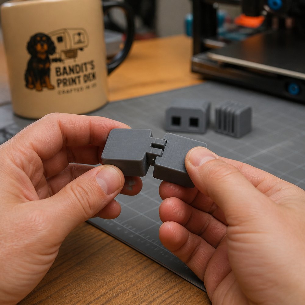
A coupon is a small test piece that isolates a single feature, a snap-fit arm and hook, a press-fit connection, a hinge and pin.
Keep coupons small.
Start From Process- and Material-Specific Clearances
There is no universal offset, the right starting clearance depends on process and material. Use these as starting points, then calibrate with your coupon.
| Process / material | Sliding fit (per side) | Snug fit (per side) | Press fit (per side) |
|---|---|---|---|
| FDM, PLA | 0.15-0.25 mm | 0.10-0.15 mm | 0.05-0.10 mm |
| FDM, PETG | 0.20-0.30 mm | 0.15-0.20 mm | 0.10-0.15 mm |
| FDM, ABS/ASA | 0.20-0.30 mm | 0.15-0.20 mm | 0.10-0.15 mm |
| FDM, TPU | 0.30-0.50 mm | 0.25-0.35 mm | Not recommended |
| Resin (SLA/DLP), standard | 0.10-0.15 mm | 0.05-0.10 mm | 0.02-0.05 mm |
| Resin, tough/ABS-like | 0.12-0.20 mm | 0.08-0.12 mm | 0.05-0.08 mm |
Why they vary: FDM nozzles lay a rounded bead that bulges at corners, so holes print undersized and posts oversized. ABS and ASA shrink more on cooling than PLA, so effective clearance changes with part size.
Measure, Adjust, and Iterate
Print your coupon and let it cool completely, PLA and PETG shrink slightly as they cool, and measuring warm parts gives you a wrong number.
Measure the actual dimensions with calipers and compare them to your CAD model.
The adjustment formula is simple:
- New hole size = target hole size + (target hole size − measured hole size)
- New pin size = target pin size − (measured pin size − target pin size)
Print and test again. Most people need two or three iterations to dial in tolerances for their printer and material.
| Test iteration | Focus | Measurement | Adjustment |
|---|---|---|---|
| Coupon 1 | Clearance sweep (9.6-10.4 mm holes) | Which hole fits the 10 mm pin? | Pick the winning clearance |
| Coupon 2 | Snap-fit arm thickness | Does it flex without cracking? | Thicken or thin by 0.2-0.3 mm |
| Coupon 3 | Press-fit depth and barb | Does it hold under pull? | Increase depth or add a barb |
| Full assembly | Overall fit | Do all joints work together? | Fine-tune problem areas only |
Diagnose and Fix Common Fit Failures
When a joint fails, separate design fixes from slicer fixes before reprinting.
- Too tight, will not assemble. Check the slicer first: flow rate or extrusion multiplier above 100 percent, or positive horizontal expansion, oversizes every feature. Reduce flow by 1 to 2 percent or set horizontal expansion negative. If the slicer is clean, add 0.1 mm to 0.2 mm of clearance in CAD and reprint the coupon.
- Too loose, falls apart. Check for under-extrusion (flow below 100 percent) or horizontal expansion that is too negative. In CAD, reduce clearance by 0.1 mm or add a small barb or detent.
- Brittle, cracks on first flex. Usually a layer-direction problem, not clearance. Reorient so the flex zone bends parallel to the layer lines, or switch from PLA to PETG. Increasing flex zone thickness by 0.2 mm also helps.
Check Fit After Printing, Not Just Before
Even a calibrated design drifts if you change layer height, nozzle size, or filament brand. After printing a full assembly, test every joint before committing to a production run. If one joint is off, reprint only that part with an adjusted clearance rather than the whole assembly, this keeps iteration cheap and your calibrated numbers honest.
Design Large Objects as Multiple Parts for Strength and Printability
A 36-inch articulated figure like our XXL Flexi T-Rex Skeleton | 36" 3D Printed Articulated Dinosaur can't print as a single piece: the bed isn't big enough and a single long piece is structurally weak.

Break it into segments. A spine becomes a series of vertebrae connected by pins; legs print separately and attach to the body; the tail is its own assembly.
Orientation, Supports, and Layer Direction
Orientation affects strength and surface quality. Layers are strong parallel to the build surface but weak perpendicular to it: a pin running horizontally is stronger than one running vertically, and a snap-fit arm that flexes parallel to layers flexes better than one flexing perpendicular.
Supports leave marks and weak spots where they attach, so orient parts to minimize support contact on functional surfaces, a snap-fit hook shouldn't have support marks, while a flat base can hide them.
Improve Assembly Strength and Durability
Interlocking parts experience stress at connection points, so reinforce them.
Consider the use case: a fidget toy flexed thousands of times needs thicker, more flexible joints, while a display piece can be tighter and more precise.
Designing interlocking 3D printed parts requires testing, iteration, and accepting that your printer won't deliver perfection.
Frequently Asked Questions
What clearance should you use for 3D-printed interlocking parts?
Clearance depends on your printer and material, but start with 0.2-0.4 mm between mating surfaces for PLA on consumer printers. Account for printer variation (typically ±0.2-0.3 mm) and material shrinkage. Test with simple coupons first, print a small test piece with your exact settings, measure the actual dimensions, and adjust your CAD model offsets before printing the full assembly. This repeatable workflow prevents costly reprints.
How do you design a snap-fit joint for 3D printing?
A snap-fit joint uses flexible geometry to create an interference fit without fasteners. Design a protruding feature (the snap) on one part and a slightly smaller receiving slot on the other. The snap bends during assembly, then springs back to lock in place. For PLA, use a 0.15-0.3 mm interference and ensure the snap arm is thin enough (1-2 mm) to flex without breaking. Test on a small coupon first to verify the snap engages and holds under your printer's settings.
Should interlocking parts be printed assembled or separately?
Print parts separately whenever possible. Printing assembled parts requires complex support structures that waste material and time, and removing supports from tight joints risks damage. Separate printing lets you orient each part for strength, print supports only where needed, and test fit before final assembly. The only exception is tiny, fragile connectors where separation would snap them, in those cases, print assembled and carefully remove supports.
How do print orientation and layer lines affect interlocking parts?
Layer lines create weakness perpendicular to the print direction. Orient interlocking parts so layers run parallel to the direction of stress (not across the joint). For a snap-fit, print the snap arm vertically so layers run along its length, not across it. Layer lines also add roughness that affects fit, if parts are too tight, rotate the part 45-90 degrees and retest. Orientation changes can recover 0.2-0.3 mm of clearance.
0 comments