
Table of Contents
- Start With a Watertight, Manifold Mesh
- 3D Printing Wall Thickness Guidelines That Prevent Weak Parts
- Dial In the Best Slicer Settings for FDM
- Tame Overhangs, Bridging, and Supports
- How to Optimize 3D Models for FDM Printing With Infill and Orientation
- Validation Workflows Before You Hit Print
- Frequently Asked Questions
Last Updated: September 14, 2026
Start With a Watertight, Manifold Mesh
Most failed prints trace back to the model, not the machine. A manifold mesh is a 3D model where every edge connects to exactly two faces and the surface forms a complete, watertight shell. If your model has gaps, flipped normals, or edges shared by three or more faces, your slicer has to guess what you meant, and guesses produce stringing, gaps, and collapsed walls.
Fixing geometry before you slice is the single highest-use habit in FDM printing. A clean mesh prints the same way every time.
Fixing Non-Manifold Geometry for Printing
Fixing non-manifold geometry for printing means locating and repairing the specific defects that break a watertight shell. The most common offenders:
- Interior faces buried inside the model
- Edges where three or more faces meet
- Holes where the surface never closed
- Duplicate or overlapping vertices
Most slicers flag these automatically. In PrusaSlicer or Cura, a model with errors shows a repair prompt before slicing. Let the tool fix simple holes, then re-export and check again. For stubborn cases, open the file in a mesh editor like Blender or Meshmixer, select non-manifold edges, and fill or dissolve them manually.
A common mistake is trusting the slicer's auto-repair to handle everything. It closes small holes well but struggles with intersecting geometry, where two separate shells overlap. Split those into distinct parts and rejoin them, or the slicer will print both surfaces and leave a mess inside the part.
3D Printing Wall Thickness Guidelines That Prevent Weak Parts
The rule that matters: a printed wall should be at least two extrusion widths thick, and ideally three. With a standard 0.4 mm nozzle and 0.4 mm extrusion width, that means walls of 0.8 mm minimum and 1.2 mm for anything that needs to hold up.
Thin walls are the number one cause of parts that look fine on the plate and snap in your hand. A single-line wall has no internal structure to resist bending, so it fails along the layer lines. Doubling the wall gives the perimeter loops something to bond to.
Practical targets for common parts:
| Part Type | Minimum Wall | Recommended Wall |
|---|---|---|
| Display figures | 0.8 mm | 1.2 mm |
| Desk accessories | 1.2 mm | 1.6 mm |
| Load-bearing brackets | 1.6 mm | 2.4 mm |
| Articulated joints | 0.8 mm | 1.0 mm |
Articulated prints are the exception to the two-width rule. Joints need clearance to move, so a single 0.4 mm wall is often correct there, provided the surrounding body is thicker. That balance between flex and strength is exactly what separates a figure that poses cleanly from one that welds itself solid.
Dial In the Best Slicer Settings for FDM
The best slicer settings for FDM are the ones matched to your model's purpose and your filament, not a universal preset. A display piece in PLA and a functional bracket in PETG want different profiles, and treating them the same wastes either time or material. Most guides stop at layer height and speed; the settings that actually decide whether a print succeeds are temperature, cooling, retraction, and flow, and they change with the material.
Layer Height, Extrusion Width, and Speed
Layer height controls the trade-off between surface finish and print time. A 0.2 mm layer is the standard middle ground on a 0.4 mm nozzle. Drop to 0.12 mm for fine detail on faces and small text; rise to 0.28 mm for rough drafts and large flat parts. A useful rule of thumb: keep layer height between 25% and 75% of nozzle diameter. Below 25% the nozzle smears the previous layer; above 75% the layers barely bond.
Extrusion width should generally match or slightly exceed your nozzle diameter. Pushing it wider than about 1.5x the nozzle diameter starves the line of material and produces gaps between perimeters. Keep it at 0.4 to 0.5 mm for a 0.4 mm nozzle. For speed, start conservative and tune upward, most desktop FDM printers run comfortably between 40 and 60 mm/s on perimeters, and pushing past that without adjusting temperature usually costs you layer adhesion.
Material-Specific Tuning (The Part Most Guides Skip)
The same model sliced for PLA, PETG, and TPU needs three different profiles. These are starting points, not gospel, every printer and filament brand varies, so run a temperature tower and a retraction test before committing a long print.
| Setting | PLA | PETG | TPU (flexible) |
|---|---|---|---|
| Nozzle temp | 200-210 C | 230-245 C | 220-235 C |
| Bed temp | 55-60 C | 75-85 C | 40-50 C |
| Part cooling fan | Full (100%) | Low (30-50%) | Very low (20-30%) |
| Retraction distance (direct drive) | 0.8-1.2 mm | 1.0-1.5 mm | 0.4-0.8 mm |
| Retraction distance (Bowden) | 4-6 mm | 4-6 mm | 2-3 mm |
| Print speed | 50-60 mm/s | 40-50 mm/s | 15-25 mm/s |
| Flow | 100% | 95-98% | 100-105% |
Why the differences matter:
- PETG bonds too aggressively to itself and to the bed. Drop flow slightly and keep the fan low so layers fuse without the part welding to the build surface. It also strings more than PLA, so longer retraction and a small z-hop help.
- TPU is flexible, so it buckles in a Bowden tube and oozes under pressure. Slow down, shorten retraction, and disable or minimize z-hop. Geometry-wise, avoid long unsupported bridges, flexible filament sags where rigid filament holds.
- PLA is the forgiving one, but it also softens near heat. Parts that sit in a hot car or near electronics need PETG or ASA instead, regardless of how well the slicer profile is tuned.
Verify Before You Commit
Slicer preview is the cheapest test you'll ever run. After setting your profile, scroll through the layer preview top to bottom and check for: floating islands with no support beneath them, walls thinner than two extrusion widths, and bridges longer than the material can span. Fixing these in the slicer costs nothing; fixing them after a failed 6-hour print costs filament and time.
Prusa Knowledge Base material and filament guides
Tame Overhangs, Bridging, and Supports
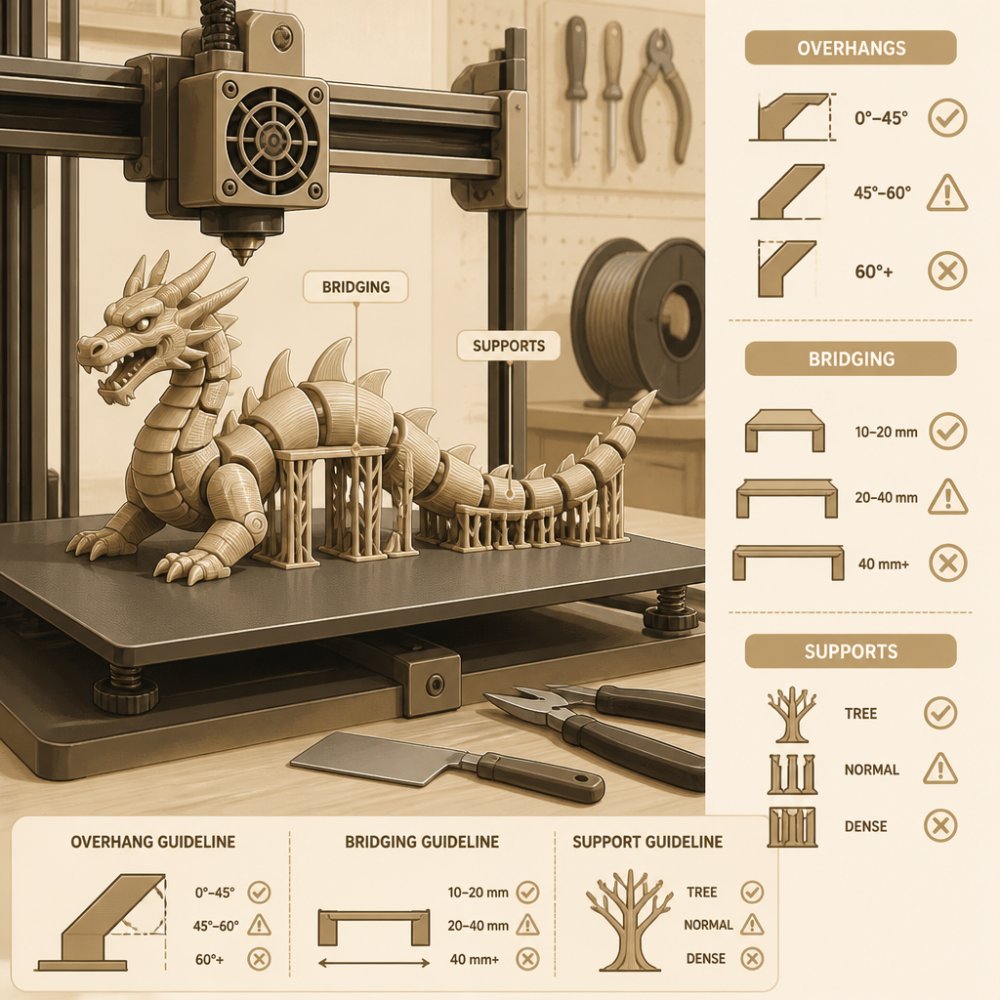
Overhangs beyond roughly 45 degrees from vertical need support, and bridging needs cooling. These two settings cause more print failures than anything else in FDM printing, and the best fix is at the model level, before you ever slice. Supports cost material, print time, and surface finish, so the goal is to design them out, not tune them in.
Fix Overhangs in CAD, Not in the Slicer
A 45-degree rule is a starting point, not a law. Modern part cooling lets many printers handle 50-60 degrees cleanly, and the exact limit depends on your fan, layer height, and material. The durable fix is geometry:
- Chamfer the underside. A 45-degree chamfer on a vertical face converts an unsupported overhang into a printable slope. This is the single highest-value DfAM move for overhangs.
- Teardrop or diamond holes. Horizontal holes print as ovals because the top of the circle sags. Model them as a teardrop (pointed top) or a diamond so the top is self-supporting, then drill or ream to size if you need a true circle.
- Rotate the part. A model that prints cleanly at one orientation may fail completely at another. Move steep angles onto faces that can print without support before you touch support settings.
- Split and reorient. If one face is unavoidably steep, cut the model into two parts, print each in its best orientation, and join them. This is often faster than printing a forest of supports.
Bridging: Cooling and Speed
A bridge is a horizontal span between two supported points. It needs fast cooling and slower extrusion to avoid sagging. Bump your part cooling fan to full for bridges and reduce bridge speed to about half your normal print speed. Keep bridge flow near 100%, starving the bridge makes it thin and weak. If the model has long unsupported spans, add a chamfer or a small rib in CAD instead of relying on the printer to bridge it. As a rough guide, most 0.4 mm-nozzle printers bridge cleanly up to about 20-30 mm; beyond that, add geometry.
Minimize Supports, Don't Just Enable Them
When supports are unavoidable, the goal is fewer contact points and easier removal:
- Use a support interface. A dense interface layer (a few solid layers) between the support and the part gives a clean underside and detaches in one piece. A tight interface gap, around 0.2 mm, lets supports release without scarring the surface.
- Prefer tree/organic supports for models with isolated overhangs. They touch the part at fewer points and use less material than a full block of support.
- Add custom support blockers in the slicer over areas that don't actually need support, so the printer doesn't build supports into cavities you'll have to dig out.
- Design internal channels for support removal. If a part has an enclosed cavity, leave an access hole so you can reach in with pliers or a pick. Designing for post-processing at the CAD stage saves far more time than any slicer tweak.
Prusa Knowledge Base guide to support material
Printing a load-bearing part flat because it's faster often creates a piece that fails at the layer lines under the first real load. Check the stress direction before you commit to an orientation.
How to Optimize 3D Models for FDM Printing With Infill and Orientation
To optimize 3D models at the slicer level, treat infill and orientation as a pair. Infill density sets internal strength; orientation sets how layers stack against the load. Get one right and the other wrong, and the part still fails.
Infill guidance by use case:
- 10-15%: display pieces, figures, anything purely decorative
- 20-25%: desk accessories and light functional parts
- 40%+: brackets and parts under real load
- Gyroid pattern: best all-round strength-to-material ratio
Orientation matters more than most people admit. FDM parts are weakest between layers, so a part loaded along the Z axis splits easily. Rotate the model so the primary stress runs along the layer plane, not across it. For a hook, that means printing it so the pull direction aligns with the layers.
Printing a load-bearing part flat because it's faster often creates a piece that fails at the layer lines under the first real load. Check the stress direction before you commit to an orientation.
Validation Workflows Before You Hit Print
A short validation pass catches most failures before they cost you filament. This is the step most people skip, and it's the one that saves the most time.
Run this checklist every time:
- Slicer reports zero manifold errors
- Wall thickness meets the two-width minimum
- Overhangs over 45 degrees have support or were rotated away
- Infill matches the part's function
- Orientation puts stress along the layer plane
- Preview the sliced layers, top to bottom, before printing
That last step catches almost everything. Scrolling through the layer preview shows you floating geometry, unsupported islands, and thin walls before the printer does. For a deeper reference on print preparation, the Ultimaker support documentation on print preparation walks through the same fundamentals.
If you'd rather skip the tuning entirely, this is where a service like Bandit's Print Den earns its keep. We print articulated figures and desk pieces on calibrated profiles, so the model arrives ready to display instead of ready to troubleshoot. Our T-Rex Dinosaur is a good example: fully articulating, printed with wall thickness and joint clearance already dialed in.

ASTM F2792 standard terminology for additive manufacturing
Getting a model to print cleanly takes more than good hardware. It takes a watertight mesh, sensible wall thickness, tuned slicer settings, and a validation pass before every job. If you'd rather spend your time displaying prints than debugging them, Bandit's Print Den handles the optimization for you, from articulated figures like our XXL Flexi T-Rex Skeleton to custom projects built to your spec. Every piece ships with the detail and finish our customers keep coming back for, and orders over $35 ship free. Get started with Bandit's Print Den and add a print-ready piece to your desk.

Frequently Asked Questions
How to optimize a 3D model for 3D printing?
Start with a watertight, manifold mesh, then set wall thickness to at least two or three extrusion widths so the shell holds up. Match layer height to your nozzle diameter, usually a quarter to three-quarters of it, and keep infill between 15 and 25% for most decorative parts. Orient the model so large flat faces sit on the plate and overhangs stay under about 45 degrees. Run a preview in your slicer to catch thin walls and floating geometry before printing.
How does wall thickness affect FDM print quality?
Wall thickness decides how rigid a part feels and how well it resists cracking along layer lines. Thin shells, under two extrusion widths, often print with gaps or gaps between perimeters. Following 3D printing wall thickness guidelines, aim for at least 1.2 mm on a 0.4 mm nozzle, and go thicker on load-bearing areas. Thicker walls also hide layer lines better and give articulated pieces like flexi dinosaurs the durability to bend without snapping.
What are the best slicer settings for FDM printing?
For most models, use a 0.2 mm layer height with a 0.4 mm nozzle, 20% infill with a gyroid or grid pattern, and three perimeters. Set print speed around 50 mm/s for outer walls and 80 to 100 mm/s for infill, then slow the first layer to 20 mm/s for adhesion. Enable retraction at 5 to 6 mm and turn on bridging detection. These baseline settings for FDM give a good balance of surface finish, print time, and part strength.
Why should I use support blockers in my slicer?
Support blockers let you stop the slicer from adding supports in spots that do not need them, like inside a hollow cavity or under a short bridge that can print on its own. Fewer supports mean less material used, faster print time, and less cleanup on the finished surface. On articulated figures, blocking supports in the joint gaps keeps the pieces from fusing together, so the model still moves after it comes off the plate.
0 comments